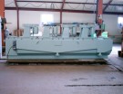
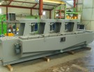
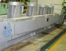
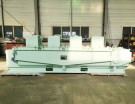
IAF Oily Water Separator
Equipment of floating type oil Removal
- Chemicals act on the process according to it’s constituent single by or dually and so increases the effect of disposal.
- 1) Emulsification destruction process
- 2) Oil constituent separation process
- 3) Cohesion process
- 4) Bubble process
- 5) The others
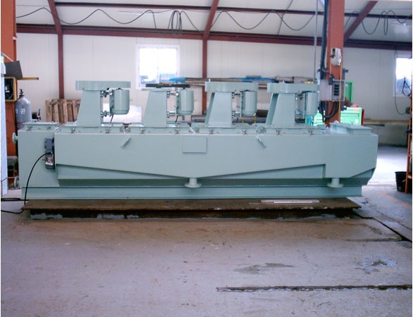
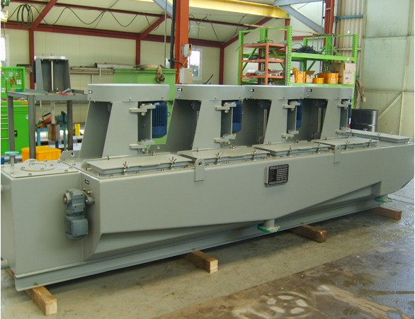
DONG HAE IAF OIL Separator is the equipment to remove the wastewater from plant, wastewater from living, SS & oil constituent.
The equipment was developed by applying to the principle of are Pressing by flotation separation. This separator pours the air unto liquid, spreads minutely and forms the microscopic bubble.
By the microscopic bubble, oil & SS constituent get to separate from water, and then floated on above of the surface of liquid.
The skimmer remove the SS & oil constituent floating above the liquid. To raise the efficiency of this process, a small quantity of chemicals is used.
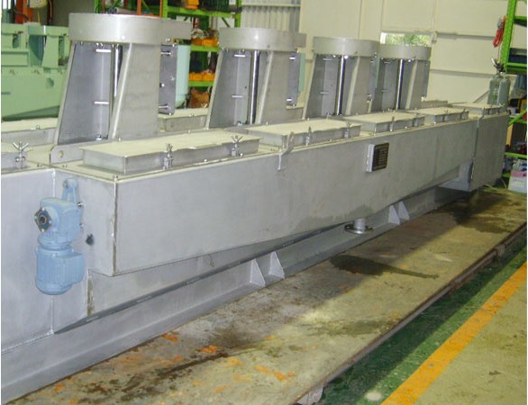
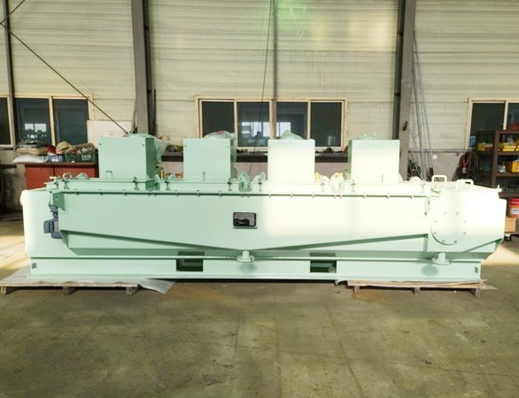
DONG HAE IAF Oil Separator consists of four cells in series connection, on each cell there installs a motor that drives a rotor.
The wastewater to be treated should pass four cells in series deposition before its discharge, and in each cell there is a partition wall extended above the liquid.
The wastewater purified in serial order moves into the next cell through the lower part of partition wall, the floating materials including oil & SS constituent gets to remove gradually with skimmer, and so more purified into the next cell in serial order.
We can see the floating material decreased gradually in accordance with the transfer cell 1to4.
On both sides of four cells, there installs a skimmer circulating at a low speed and a path to flow over the floating material discharged by skimmer beside the skimmer.
In case of treating an illsmelling waste liquid or an explosive gas, it's possible to pour into N² gas instead of air, by covering up the whole part tight.
Specification
※ You can check the contents by scrolling left/right.
| MODEL No. |
CAPACITY OF STANDARD (m³/hr) |
DIMENSION (LXWXH)(M) |
INSPECTION HEIGHT (M) |
WEIGHT (TON) |
OPERATED WEIGHT (TON) |
|---|---|---|---|---|---|
| DHIAF-10 | 10 | 4.4 X 1.1 X 1.5 | 2.1 | 2.7 | 3.6 |
| DHIAF-30 | 30 | 6.5 X 1.5 X 2.0 | 2.7 | 4.7 | 7.3 |
| DHIAF-70 | 70 | 8.1 X 1.8 X 2.0 | 2.9 | 5.7 | 10.7 |
| DHIAF-100 | 100 | 9.4 X 2.0 X 2.1 | 3.0 | 7.1 | 14.6 |
| DHIAF-170 | 170 | 9.7 X 2.5 X 2.7 | 3.0 | 9.9 | 22.4 |
| DHIAF-250 | 250 | 10.9 X 2.5 X 2.7 | 3.7 | 11.4 | 30.1 |
| DHIAF-500 | 500 | 12.4 X 3.7 X 3.3 | 4.6 | 16.9 | 54.3 |
| DHIAF-680 | 680 | 16.3 X 3.7 X 3.3 | 4.6 | 19.0 | 68.8 |
| DHIAF-1120 | 1120 | 16.3 X 3.7 X 3.7 | 5.2 | 29.1 | 111.3 |

